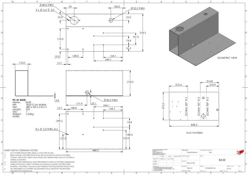
A finished SolidWorks sheet-metal model is not the same as a fabrication-ready design.
The model may fold perfectly on screen, but the drawing still needs to clearly communicate how the part should be manufactured.
A useful sheet-metal drawing should typically include:
• Material grade and thickness
• Finished-part and flat-pattern views
• Bend direction, angle and internal radius
• Critical dimensions from stable datums
• Grain direction where relevant
• Surface finish or coating requirements
• Deburring and edge-break notes
• Weld details, inserts and hardware
• A clean DXF with bend lines clearly identified
It is also worth checking that the bend allowance, K-factor and tooling assumptions reflect the fabricator’s actual process.
A small drafting omission can result in the part being folded backwards, dimensions shifting after bending, inserts being installed on the wrong face, or a flat pattern that cannot be produced using available tooling.
Good sheet-metal design is not just about creating the geometry.
It is about giving the fabricator everything they need to make the part correctly the first time.